UDBCoordinateSystems
Peter Hollands, December 2009 with thanks to William Premerlani for detailed review and corrections.
The software inside of the UAV DevBoard uses 4 coordinate systems.
These are:-
- Aviation Convention - Airplane
- Aviation Convention - Earth
- UAV DevBoard – Earth
- GPS Convention – Lat / Lon
Why 4? In summary, it is because UAV DevBoard has been a learning journey for the team. If we started again, we could make this slightly simpler, but at this stage, it is easier to leave the software as it is, and to provide you with this document.
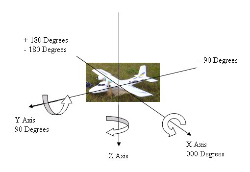
We use a variation of the aviation convention for the coordinates for vectors measured in the frame of reference of the plane, such as accelerometer and gyro signals. It is not exactly the same as the standard aviation convention. It came out the way simply because the design of the board included X and Y arrow labels that agreed with the mounting of the three-axis accelerometer on the board. Since then, we discovered that the industry standard aviation convention is rotated 90 degrees from the aviation convention used in the UAV DevBoard firmware.
There is a supporting document to this document which explains the mathematics that is used by the UAV DevBoard firmware. That document is called the Direction Cosine Matrix IMU: Theory. See http://gentlenav.googlecode.com/files/DCMDraft2.pdf . The X and Y axis in the Theory document are the reverse of this document.
In the system used for UAV DevBoard, angles are defined using the mathematical convention. Positive angles are measured counter-clockwise when looking along an axis toward the origin. For example, a positive pitch angle change corresponds to the plane pitching downward.
Some of the Z angles are shown in the previous figure, which are measured from the X axis. X and Y angles are not shown. Another way of describing how angles are measured is that angles follow the “right hand rule”. That is, if you take your right hand, and place your thumb in the direction of any axis, then your remaining fingers, when slightly clenched will point in the direction of a positive angle around that axis.
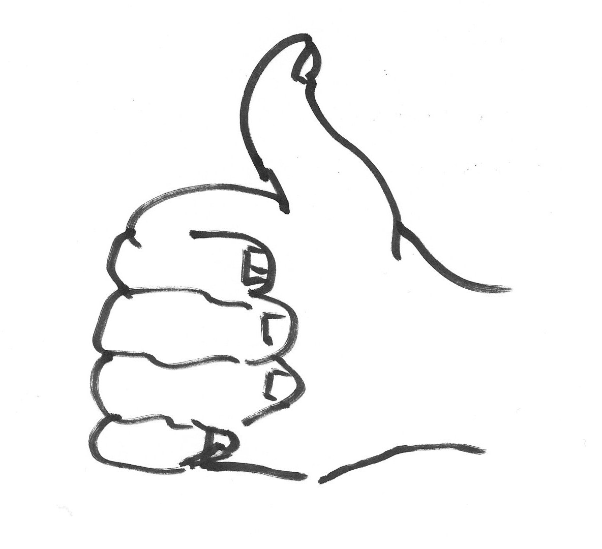
This hand would need to be rotated down so that the thumb points downwards in line with the positive direction of the Z axis.

Aviation Convention – Earth is exactly the same as Aviation Convention – Plane. It is just that the two coordinate systems move independently as the plane banks, turns, dives and “loops the loop” around the sky. The two coordinate systems can be related to each other by a mathematical “translation” of the origins of each coordinate system and by a rotation. The latter rotation is specified by the Direction Cosine Matrix, also known as “rmat” (rotation matrix) in the firmware of the UAV DevBoard. The Aviation Convention – Plane coordinate system coincides with the Aviation Convention – Earth coordinate system when the plane is located at the origin of the Aviation Convention – Earth coordinate system, pointing north, with the plane level with respect to both pitch and roll.
The mathematics of this approach is described in a document called Direction Cosine Matrix IMU: Theory. (see http://gentlenav.googlecode.com/files/DCMDraft2.pdf ) . Note, as also mentioned above, that this document was written before the axis labels were printed on the UAV DevBoard manufactured by Spark Fun, and so the X and Y axis in that document are the reverse of this document.
This coordinate system is used by software within the UAV DevBoard to represent relative distances from where the plane’s computer was started up. Using relative distances, allows the computer to save on memory and CPU cycles as the variables can then be sized as 16 bit variables, rather than 32 bit variables. (Note that 16 bit values mean that the computer can travel at most 2 to the power 15 the 16th bit is the sign bit i.e. 32768 meters or 20.36 miles from it’s origin before navigation variables will overflow. )

Distances along the X axis and Y axis are measured in meters from the location where the plane first acquired a GPS location. This is usually the place where the plane’s UAV DevBoard is started up on the airfield. Note that the X Axis of UAV DevBoard – Earth is reversed when compared to Aviation Convention – Earth.
Positive Z is the height of the plane above where it first was started up. The Z axis of UAV DevBoard – Earth is the reverse of that which is used for Aviation Convention – Earth.
Angles in the UAV DevBoard system are measured in the mathematical convention of counter clockwise, starting from the east. So this convention is also using the right hand rule.

This coordinate system is the normal navigational convention used by shipping and aircraft since the seventeenth century. We use it because we receive positional information from the Global Positioning System (GPS) in this format.
We will now explore how the UAV DevBoard firmware converts between coordinate systems. In this section all links to actual code are links to revision 202 (on Google Code) of MatrixPilot.
As an example, we will take the most extreme case of conversion that is required. That is the case when the UAV DevBoard is controlling servos on the plane to point a camera at a known GPS location on the ground. The plane might be upside down, undertaking aerobatics as it is taking pictures, but the UAV DevBoard software can keep the camera pointing in the right direction.(subject to the mechanical abilities of the servos).
The firmware receives the position of the plane as Lat, Long and Altitude information from a GPS receiver. For example: +524744707 latitude -10948199 longitude, 7800 altitude. Lat and Long are delivered to the code by a routine called commit_gps_data. Lat and Long are delivered multiplied by 10 to the power 7. Altitude is delivered as meters multiplied by 100. So the above locations are in fact +52.4744707 latitude, -1.0948199 longitude and78.00 meters. This data is framed within the GPS Convention – Lat / Lon discussed above.
A new aircraft position is received from the GPS. The code in gpsParseCommon.c calls a routine called navigate() which converts this data into the coordinate system called UAV DevBoard – Earth. Here is a fragment of that code:-
// in meters, range is about 20 miles

accum_nav.WW = ((lat_gps.WW - lat_origin.WW)/90) ; vector_to_origin.y =  \

                              - accum_nav._.W0 ;

GPSlocation.y = accum_nav._.W0 ;


heightlong.WW = ( alt_sl_gps.WW - alt_origin.WW)/100 ; // height in meters

height = heightlong._.W0 ;

GPSlocation.z = height ;


//      multiply the longitude delta by the cosine of the latitude

accum_nav.WW = ((long_gps.WW - long_origin.WW)/90) ; // in meters

accum_nav.WW = ((__builtin_mulss ( cos_lat , accum_nav._.W0 )<<2)) ;

vector_to_origin.x = - accum_nav._.W1 ;

GPSlocation.x = accum_nav._.W1
The code uses a 32 bit temporary variable called accum_nav.WW to subtract the latitude at start-up (lat_origin) from its current location (lat_gps). The result when divide by 90 converts the difference in latitude into meters. Keeping the difference as a 32 bit quantity is no longer required as the amount will be relatively small.
GPSlocation.y = accum_nav._.W0 ;
will take the bottom 16 bits of the distance from the origin and store it as the variable GPSlocation.y . So latitude in the GPS Convention Lat / Lon converts easily to the Y axis of the UAV DevBoard - Earth. No change of sign is required.
A similar process is done for the longitude. However the distance associated with a change in longitude depends at what latitude the distance is measured. If you think about it for a moment, one can move through 180 degrees of longitude at the North Pole and travel no distance. You can simply turn around. While 180 degrees of longitude traveled at the equator is more than 12000 miles. So in the code above, the code first finds the difference in longitude:
accum_nav.WW = ((long_gps.WW - long_origin.WW)/90) ;
and then multiplies that answer by the cosine of the latitude. So at the North Pole, where the latitude is 90 degrees, the cosine would be 0, and so the distance moved would be correctly computed as 0. While at the equator, where the latitude is 0, the cosine would be 1, and the distance would remain exactly as computed on the previous line.
So to summarize: Coordinate conversion from GPS Convention – Lat / Lon to UAV DevBoard – Earth is easy. The axis of both conventions are aligned and in the same direction. The only small complication it that the distance moved by a change in longitude depends partly on what latitude the plane is at.
For completeness, I’m going to also discuss the conversion of angles. This is not required for the camera example above, but it is required for correcting yaw gyro drift using the Course Over the Ground (COG) from the GPS. COG is received from the GPS as a value like 32679 in the routine commit_gps_data() . That means a course of 326.79 degrees. It is converted from GPS Convention – Lat / Lon to UAV DevBoard - Earth in the routine called estYawDrift(). Two lines achieve the conversion:-
accum.WW = __builtin_muluu ( COURSEDEG_2_BYTECIR , cog_gps.BB ) ;

actual_dir = -accum.__.B2 + 64 ;
The first line converts the angle from degrees to ByteCircular. Degrees represents angle in a circle from 0 -360 degrees. ByteCircular represents angles in a circle with values from 0-255. One ByteCircular is equal to around 1.4 degrees.
The second line reverse the direction of the angle (negates the angle), and then adds on 90 degrees which is 64 in ByteCircular. If you look carefully at the convention diagrams above, you can confirm that due north is 000 in the GPS Convention – Lat / Lon and is 90 Degrees (or more specifically + 64 ByteCircular) in the UAV DevBoard – Earth convention.
The desired location to view with the camera was 40 meters north and 20 meters east of the origin at start-up. The code in waypoints.c could look something like:-
void compute_camera_view (void)

{

// For now camera view_location set here and not in waypoints.h

// The following are in meters and are relative to the origin.


// view location is 20 meters to the east of where the plane starts up.

	view_location.x = 20  ;

	view_location.y = 40

	view_location.z = 0;


	camera_view.x = (view_location.x - GPSlocation.x);


	camera_view.y =  (view_location.y - GPSlocation.y) ;

	camera_view.z =  (view_location.z - GPSlocation.z) ;

}
That vector, in order to be useful for pointing the camera on the plane, needs to be converted first to the Aviation Convention – Ground reference, and then rotated into the Aviation Convention – Airplane reference.
For a vector, that simply means swapping the signs of the X axis and the Z axis. The figure below shows this quite clearly.

To convert from the Aviation Convention - Earth convention to the UAV DevBoard - Earth, values of Y remain the same. Values of X must be negated (The X axis of the plane is opposite to that of the ground). Values for Z must also be negated.
With regard to yaw angles measured in each system: basically, the two coordinates are flipped 180 degrees with respect to each other, so they rotate in opposite directions, starting 180 degrees apart.
In the code for pointing the camera, this could be done in cameraCntrl.c as follows:-
// Convert from "UAV DevBoard - Earth" convention to "Aviation Convention - Earth"

cam_vector_ground[0] = - camera_view.x ;

cam_vector_ground[1] =   camera_view.y ;

cam_vector_ground[2] = - camera_view.z ;
The servos in the plane are aligned with the axis in the Aviation Convention – Airlane. It is easiest to set the servos, if the cam_vector_ground is now converted into that coordinate system. This is easily achieved by using the Direction Cosines Matrix which is constantly tracking the relative rotation between the Aviation Convention – Airlane Axes and the Aviation Convention – Ground Axes. We simply need to take the inverse (which is also the transpose) of the rotation matrix, rmat, and multiply that inverse rotation onto the cam_vector_ground. Here is some code that will do that:-
MatrixTranspose(3, 3, rmat_transpose, rmat ) ;

// It does not matter that the result of this operation is not the expected magnitude

// The code only uses the ratios of X,Y,Z relative to each other to calculate angles.

MatrixMultiply( 3 , 3 , 1 , cam_vector_plane , \

       rmat_transpose ,cam_vector_ground ) ;
So we now have the vector that points at the camera in the plane’s coordinate reference system. It is called cam_vector_plane.
The two Aviation Conventions are completely similar apart from rotations of their axis. So no further conversion is necessary.
To summarize: Conversion from Aviation Convention – Earth to Aviation Convention – Airplane of vectors is simply a question of multiplying the inverse of the rotation matrix, rmat .
However, to point the turret servo in the right direction, there is yet still another conversion that must be done. Aviation Convention – Airlane, would have a yaw angle as 0 as pointing out down the left wing (the X axis). But normal usage of the word yaw would have a yaw angle of 0 with reference to the plane as pointing directly forward of the plane in line with the fuselage. This the natural yaw angle to use for a turret servo that is going to point in proportion to the cam_vector plane. So we now have to subtract 90 degrees onto any heading angle calculated from Aviation Convention – Airlane, in order to make it line up with the fuselage. This 90 degree rotation is achieved in the code below, by subtracting 64 units of ByteCircular (90 degrees) onto the yaw.
// Yaw

	matrix_accum.x =   cam_vector_plane[0] ;

	matrix_accum.y =   cam_vector_plane[1] ;

	yaw = rect_to_polar(&matrix_accum) - 64; // subtract 90 degrees

	// Pitch

	matrix_accum.y = cam_vector_plane[2] ;

	pitch = rect_to_polar(&matrix_accum) ;
The yaw and pitch in this calculation relate entirely to the plane’s of reference. They determine the angle of pitch and yaw relative to the plane to achieve the to desired camera view.
The Rmat rotational matrix has converted a desired camera vector based on the earth’s reference, into a desired vector with reference to the plane’s axis, and finally converted that into yaw and pitch angles.(The software does this 40 times / second). These values of yaw and pitch, will always point at the right location on the earth. So now it is now a fairly simple exercise to rotate the camera servos, which are also operating relative to the plane.
For pitch the key line of code is:-
cam.WW = __builtin_mulss((pitchServoLimit(pitch - pitch_offset_centred)), pitch_servo_ratio) ;
and for yaw the key line of code is:-
cam.WW = __builtin_mulss((yawServoLimit(yaw - yaw_offset_centred)), yaw_servo_ratio) ;
So there are primarily 4 coordinate systems in use in the UAV DevBoard:
- Aviation Convention - Airplane
- Aviation Convention - Earth
- UAV DevBoard – Earth
- GPS Convention – Lat / Lon
With the camera example, we have traversed those systems in reverse order to show how each coordinate system relates to the previous one.