HowToInstall
If you're going to be using more than the built in 4 RC inputs and 3 RC outputs, or if you plan to use the MatrixPilot OSD, you'll want to solder male headers onto the 4 through-holes for RE4, RE2, RE0, RE8. If you plan to connect an OpenLog, or view telemetry data, you should solder male headers onto the 4 pins next to those (VCC, TXO, RXI, GND). In general, I suggest just soldering an 8-pin male header onto that whole row.
The UDB4 comes without any through-hole pins pre-soldered. This gives you more flexibility on what kinds, and how many headers you want to connect to the board.
For RC Inputs, there are a few good options. If you plan to use a PPM connection from your RC receiver to the UDB4, you only need to connect one servo cable to In1, so just solder a single 3-pin header to In1. You can even use a right-angle header here, to keep the connection low-profile. If you plan to connect each channel directly from your RC receiver to the UDB4, there are 2 good options. The simplest is to just add N 3-pin male headers to the first N Input channels on the UDB4, where N is the number of input channels you want to connect. (Up to 8.) A nice weight-saving (and cable-clutter-saving) shortcut is to connect just one VCC and GND pair from the RC Receiver to the UDB4, and then connect only the signal lines for the all of the channels, in groups of 3, using standard servo cables. The pins are grouped and spaced so that you can connect channels 1-3, 4-6, and 7-8, each as groups of 3, 3, and 2, using standard 0.1" cables, like standard servo cables. This will only work if your RC RX has standard 0.1" spaced pins.
For RC Outputs, just add N 3-pin male headers to the first N output channels on the UDB4, where N is the number of servos (including throttle ESC) that you want to connect.
You'll also need to connect a 6 pin male header to the ICSP port. This is where you'll connect a PIC programmer like the PicKit3. (Fun fact: only the first 5 are actually necessary for the UDB boards. That's the 5 pins furthest from the Servo Outputs.) Note that pin 1 of the ICSP port is the pin closest to the center of the UDB4.
And you'll probably also want to use logging or telemetry of some sort. If so you should add a 4-pin header to the 4 adjacent pins labelled TX2, RX2, 3.3, GND.
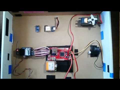
It is a good idea to test out your UDB setup on the bench before installing it in a plane for the first time. The video below, by Phil Giacalone is an excellent introduction to the UDB4 connections, and operations, using his bench setup.
Install the board in your plane with the GPS connector facing forward and the components facing up. Or in one of the other orientations defined in the options.h file.
The board should be installed to that it will be level when the plane is flying. Depending on your plane, this might not line up with the bottom or top edges of the fuselage.
If you are using the UDB2 (red board with 2 vertical daughter boards), and you expect some vibration, you may want to mount the board to your plane using a couple layers of gyro-mounting foam tape.
Try to position the UDB away from heat sources. The biggest heat sources in most electric planes is the ESC. Some people do this by mounting the UDB inside the fuselage, and moving the ESC outside of it, to the top of the fuselage.
Next, connect the GPS to the board, and find a place to install the GPS into the plane. It should point up, and have a clear view of the sky. The GPS will likely work best if it is mounted on top of the plane, as opposed to inside the fuselage. For the UDB4, make sure to connect the GPS to the correct GPS port. Right now, the 3.3V uBlox GPS (with no adapter board) plugs into the D2523T connector. The EM406, 5V uBlox, and DIYDrones MediaTek GPS all plug into the port labelled EM406.
By default, the firmware is set up to expect the following Radio/Servo connections, although this can all be configured in the options.h file of the firmware:
- Aileron control. Connect whatever channel on your Rx that you like to use for the ailerons to channel 1 input on the board.
- Elevator control. Connect whatever channel on your Rx that you like to use for elevator to channel 2 input on the board.
- Throttle control. If you are using altitude hold, connect whatever channel on your Rx that you like to use for throttle to channel 3 input on the board. If you are not using altitude hold, connect the throttle servo or ESC input directly to the Rx.
- Manual/Stabilized/WayPoint mode control. Connect whatever channel on your Rx that you are going to use for mode control to channel 4 input on the board. A 3-way switch works best.
- Connect servo 1 output from the board to your aileron servos.
- Connect servo 2 output from the board to your elevator servo.
- If you are using altitude hold, connect servo 3 output from the board to your throttle servo or electronic speed control.
The ordering of the pins on the board are the ground connections are nearest the edge of the board, the power connection is in the middle, and the signal is farthest from the edge. If you are using cables with black-red-white wires, the black wire connects closest to the edge. If you are using cables with brown-red-orange wires, the brown wire connects closest to the edge. Connections from the board PWM input channels to your radio will require special cables with female connectors on both ends.
For a UDB2/3: If you want to use the Extra Channels on the board, check out the ConnectingExtraChannels page, and then connect any of the following connections you want:
- Rudder control. Connect whatever channel on your Rx that you like to use for rudder to channel 5 input (RE8) on the board.
- Connect servo 4 output (RE0) from the board to your rudder servo.
- Connect servo 2 output (RE2) from the board to your 2nd aileron servo. (This servo is separately reversible.)
As of MatrixPilot 3.0, it is also possible to use a PPM Encoder board to allow up to 8 RC inputs to come into the UDB through one servo cable attached to IN4 on a UDB2/3, or to IN1 on the UDB4. On a UDB2/3, this leaves you with up to 6 proper output servo connectors (by using In1-In3 as additional outputs) and the 3 extra servo outputs on pins RE0, RE2, and RE4.
If you are installing the board deep inside your plane in a hard to reach spot, you'll probably want to attach a programming cable to the 6-pin programming header on the board, so you can adjust your control gains and upgrade the firmware without pulling the board out.
Once this is all set up, make sure MatrixPilot is configured well for your plane, and make sure to do an initial ground-test of everything. It might be best to do it outside to get a faster GPS lock.
The UDB is usually powered the same way you would normally power the RC Receiver -- just plug your ESC's throttle cable (standard 3-wire servo cable) into the UDB's Out3 channel. If your ESC includes a BEC, then you're done powering the board. If not, then you should power the board some other way. The UDB4 includes an extra set of +/- pins for this purpose.
The UDB4 also has a small solder jumper between Out8 and the ICSP port, that allows separating the servo power bus from the rest of the board. This jumper defaults to being connected. If you disconnect it, then you'll have to power the UDB from one of the RC Inputs, and can power your servos from the spare +/- pins. The benefit to separating the servo power from the rest of the board is that otherwise, if you have many power-hungry servos, then despite our careful UDB4 power supply design, you can get voltage dips that could possibly cause the UDB to reboot during flight (which would leave you with only manual control). Separating the servo power solves this problem.